Modern aluminum electrolysis utilizes the cryolite-alumina molten salt electrolysis method. Alumina is used as the solute, carbonaceous material as the anode, and molten aluminum as the cathode. A strong direct current from a rectifier cabinet is applied, and an electrochemical reaction occurs at the electrodes within the electrolytic cell at 950℃-970℃—this is aluminum electrolysis. The compatibility of the rectifier equipment significantly impacts aluminum quality and electricity costs. A complete rectifier system includes a rectifier cabinet, digital control cabinet, rectifier transformer, pure water cooler, DC sensors, and DC switches. It is typically installed indoors near the electrolytic cell, using pure water cooling, and has input voltages of 220KV, 10KV, etc.
I. Applications
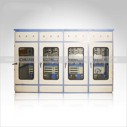
This series of rectifier cabinets is mainly used in various types of rectifier equipment and automated control systems for the electrolysis of non-ferrous metals such as aluminum, magnesium, manganese, zinc, copper, and lead, as well as chloride salts. It can also serve as a power supply for similar loads.
I. Applications
This series of rectifier cabinets is mainly used in different types of rectifier equipment and automated control systems for the electrolysis of non-ferrous metals such as aluminum, magnesium, manganese, zinc, copper, and lead, as well as chloride salts. II. Main Cabinet Features
1. Electrical Connection Type: Generally selected based on DC voltage, current, and grid harmonic tolerances, with two main categories: double-star and three-phase bridge, and four different combinations including six-pulse and twelve-pulse connections.
2. High-power thyristors are used to reduce the number of parallel components, simplifying the cabinet structure, reducing losses, and facilitating maintenance.
3. Components and fast-fusing copper busbars use specially designed circulating water circuit profiles for optimal heat dissipation and extended component lifespan.
4. Component press-fitting employs a typical design for balanced and fixed stress, with double insulation.
5. Internal water pipes use imported reinforced transparent soft plastic tubing, resistant to both hot and cold temperatures, and with a long service life.
6. Component radiator faucets undergo special treatment for corrosion resistance.
7. The cabinet is fully CNC machined and powder-coated for an aesthetically pleasing appearance.
8. Cabinets are generally available in indoor open, semi-open, and outdoor fully sealed types; cable entry and exit methods are designed according to user requirements.
9. This series of rectifier cabinets adopts a digital industrial control trigger control system, enabling the equipment to
III. Technical Characteristics
1. Regulator: The digital regulator offers flexible and variable control modes and stable characteristics, while the analog regulator provides rapid response. Both employ DC current negative feedback control, achieving a current stabilization accuracy better than ±0.5%.
2. Digital Trigger: Outputs 6-phase or 12-phase trigger pulses, with a double narrow pulse pattern spaced 60° apart, strong trigger waveform, phase asymmetry ≤ ±0.3°, phase shift range 0~150°, and single-phase AC synchronization. High pulse symmetry.
3. Operation: Touch key operation for start-up, stop-up, and current adjustment.
4. Protection: Includes no-current start, two-stage DC overcurrent alarm protection, feedback signal loss protection, water pressure and temperature over-limit protection, process interlock protection, and operating control angle over-limit indication. It can also automatically adjust the transformer tap position according to the control angle.
5. Display: Utilizes an LCD display to show various parameters, including DC current, DC voltage, water pressure, water temperature, oil temperature, and control angle.
6. Dual-channel product: During operation, the two channels serve as hot standby for each other, allowing for maintenance without shutdown and seamless switching without current disturbance. 7. Network Communication: Supports multiple communication protocols including Modbus, Profibus, and Eathernet.
Voltage Specifications:
16V 36V 75V 100V 125V 160V 200V 315V 400V 500V 630V 800V 1000V 1200V 1400V
Current Specifications:
300A 750A 1000A 2000A 3150A 5000A 6300A 8000A 10000A 16000A 20000A 25000A 31500A 40000A 50000A
63000A 80000A 100000A 120000A 160000A
Functional Description
◆ Small Dummy Load: A section of heating element is connected to replace the actual load, ensuring a DC current of 10-20A when the output is at rated DC voltage.
◆ Intelligent Thermal Redundancy Control System: Two CNC controllers are interconnected via thermal redundancy ports, coordinating control in parallel without any control contention or exclusion. Seamless switching between master and slave controllers.
If the master controller fails, the redundant controller automatically and seamlessly switches to become the master controller, truly achieving dual-channel thermal redundancy control. This greatly improves the reliability of the control system.
◆ Seamless Master/Redundancy Switching: Two ZCH-12 control systems with mutual thermal redundancy can be manually configured to determine which controller acts as the master and which as the slave. The switching process is seamless.
◆ Redundancy Switching: If the master controller fails due to an internal fault, the redundant controller automatically and seamlessly switches to become the master controller.
◆Impulzusadaptív főáramkör: Amikor egy kis álterhelést csatlakoztatnak a főáramkörhöz, és a feszültség-visszacsatolás amplitúdóját 5-8 voltos tartományon belül állítják be, a ZCH-12 automatikusan beállítja az impulzus kezdőpontját, végpontját, fáziseltolódási tartományát és impulzuseloszlás-szekvenciáját, hogy az impulzus fáziseltolódása adaptív legyen a főáramkörhöz. Nincs szükség kézi beavatkozásra, így pontosabb, mint a kézi beállítás.
◆Impulzusórajel-szám kiválasztása: Az impulzusórajel-szám kiválasztásával az impulzus alkalmazkodhat a főáramkör fázisához, és helyesen eltolhatja a fázist.
◆Impulzusfázis finomhangolás: Az impulzusfázis finomhangolásával az impulzus pontosan igazítható a főáramkör fáziseltolódásához, ≤1°-os hibával. A finomhangolás értéktartománya -15° és +15° között van.
◆Kétcsoportos impulzusfázis-beállítás: Módosítja az első és a második impulzuscsoport közötti fáziskülönbséget. A beállítási érték nulla, az első és a második impulzuscsoport közötti fáziskülönbség pedig 30°. A beállítási érték tartománya -15° és +15° között van.
◆Az 1F csatorna az áram-visszacsatolás egy csoportjaként van kijelölve. A 2F csatorna az áram-visszacsatolás két csoportjaként van kijelölve.
◆Automatikus árammegosztás: A ZCH-12 automatikusan, manuális beavatkozás nélkül beállítja magát az első és második áram-visszacsatolási csoport eltérése alapján. A manuális árammegosztás manuálisan érhető el a csillag és a két csoport közötti árammegosztás beállításával.
◆Zökkenőmentes váltás: A teljesítmény a váltás során változatlan marad.
◆Vészleállító funkció: Amikor az FS csatlakozó rövidre záródik a 0V-os csatlakozóval, a ZCH-12 azonnal leállítja a trigger impulzusok küldését. Ha az FS csatlakozót lebegően hagyjuk, a trigger impulzusok küldése megtörténik.
◆Lágyindítás funkció: A ZCH-12 bekapcsolásakor az önteszt után a kimenet lassan emelkedik a megadott értékre. A standard lágyindítási idő 5 másodperc. Az egyéni idő beállítható.
◆Nullapont-visszatérés védelmi funkció: Bekapcsoláskor, az önellenőrzés után, ha a megadott érték nem nulla, nem ad ki trigger impulzust. A normál működés akkor folytatódik, amikor a megadott érték visszatér nullára.
◆ZCH-12 szoftveres visszaállítás: A ZCH-12 visszaállítása szoftverprogramparancs végrehajtásával történik.
◆ZCH-12 hardveres visszaállítás: A ZCH-12 hardveresen visszaállítható.
◆Fázisváltási tartomány kiválasztása: 0. tartomány~3. 0: 120°, 1: 150°, 2: 180°, 3: 90°
◆Állandó paramétermentés: A CNC hibakeresés során módosított vezérlési paraméterek a RAM-ban tárolódnak, és áramkimaradás esetén elvesznek. A hibakeresett vezérlési paraméterek végleges mentéséhez: ① Állítsa az SW1 és SW2 1-8. bitjeit OFF, OFF, OFF, OFF, OFF, ON, OFF, OFF értékre a mentés engedélyezéséhez;
②Engedélyezze az állandó paramétermentési funkciót; ③ Állítsa az SW1 és SW2 1-8. bitjeit KI állásba a mentés letiltásához.
◆PID paraméter automatikus hangolása: A vezérlő automatikusan méri a terhelési jellemzőket, hogy megkapja a terheléshez optimális algoritmust. Ez pontosabb, mint a kézi beállítás. Speciális terhelések esetén, ahol a terhelési jellemzők összefüggenek a terhelési körülményekkel és nagymértékben változnak, a PID csak manuálisan hangolható.
◆PID szabályozó kiválasztása:
A PID0 egy dinamikus, gyors PID-szabályozó, amely alkalmas ohmos terhelésekhez.
A PID1 egy közepes sebességű PID-szabályozó, kiváló általános automatikus beállítási teljesítménnyel, amely alkalmas ohmos-kapacitív és ohmos-induktív terhelésekhez.
A PID2 alkalmas nagy tehetetlenségű szabályozott objektumokhoz, például kapacitív terhelések feszültségszabályozására és induktív terhelések áramszabályozására.
A PID3–PID7 manuális PID-szabályozók, amelyek lehetővé teszik a P, I és D paraméterek értékeinek manuális beállítását. A PID8 és PID9 speciális terhelésekhez testreszabott.